
The Hidden Fault: Severing an Active Ground Path
A fatal shortcut: Why unbolting a ground wire during an active fault turns the troubleshooter into the ground path.
1. The Flashpoint
At 2:15 PM inside a heavy manufacturing plant, an electrician unbolted a main equipment grounding conductor (EGC) to isolate a section of a 480V Motor Control Center. The moment the copper lug separated from the ground bus, the full 277V potential spiked across the open gap, instantly turning the electrician’s body into the new fault path to earth and delivering a sustained, fatal shock.
2. Context & Environment
The plant had been experiencing unexplained objectionable current on the grounding system and communication noise on their Control network for the past three weeks. Management suspected a circulating ground loop, causing a low-voltage differential across the facility’s grounding array.
The task assigned to the senior electrician was to systematically isolate sections of the grounding grid at the MCC to pinpoint the source of the noise. It was a Friday afternoon, and he had been working a punishing 60-hour week. Failing to recognize the potential danger of an active fault returning on the grounding system, he bypassed verifying the wire with a clamp meter before touching it. He wore standard leather gloves, assuming they were dealing with purely structural safety bonding.
3. Chronological Forensics
The electrician knelt in front of the MCC ground bus. What he didn’t know was that a 50HP pump motor out in the plant had suffered an insulation failure earlier that morning. One phase of the 480V supply was actively shorted to the motor’s metal casing. Because it was a high-impedance fault and the system was aging, the breaker had not tripped.
- The fault current was continuously flowing from the motor casing, back through the facility’s grounding network, up the specific EGC the electrician was touching, and back to the transformer neutral.
- The electrician placed his bare left hand on the steel MCC enclosure to steady himself.
- With his right hand, he used a socket wrench to unscrew the 1/0 copper EGC lug from the busbar.
- As he pulled the lug away, he broke the circuit.
- The only remaining parallel path to the transformer neutral was through his body — roughly 1,000 Ω from hand to hand.
- The full 277V phase-to-ground potential drove current directly through his chest. He did not see “277V across an open gap.” He became the open gap.
Guess the Root Cause
Why did the voltage suddenly spike to 277V the moment the ground wire was disconnected?
4. Root Cause Analysis
Direct Cause The electrician inserted himself in series with an active ground fault by breaking an equipment grounding conductor that was actively carrying returning fault current.
Systemic/Human Cause A deeply ingrained complacency regarding ground wires. Many technicians and electricians assume that green or bare wires are inherently safe and “dead” because their nominal function is just for emergency bonding. Time constraints and fatigue overrode standard verification protocols — a simple 5-second check with a clamp meter would have revealed the wire was carrying amperes of fault current, instantly warning the technician. Upstream of this: the facility had no ground-fault protection of equipment (GFPE) on the feeder, no continuous ground-current monitoring, and no work-planning procedure that classified grounding-system work on an energized distribution system as energized electrical work.
5. Relevant Codes & Standards
- NEC 250.4(A)(5) / CEC Rule 10-500 (Effective Ground-Fault Current Path)
- NEC 230.95 / CEC Rule 14-102 (Ground-Fault Protection of Equipment)
- IEEE 142 (Green Book) — Objectionable Current on the Grounding System
- NFPA 70E Article 130 / CSA Z462 Clause 4.3 (Working On or Near Live Parts)
6. Failure Modes and Effects Analysis (FMEA)
Every significant failure mode in this incident — from the motor insulation breakdown that started the fault, to the procedural gaps that ended in a fatality — mapped to cause, effect, severity, and the control that would have broken the chain. Click to open the full analysis.
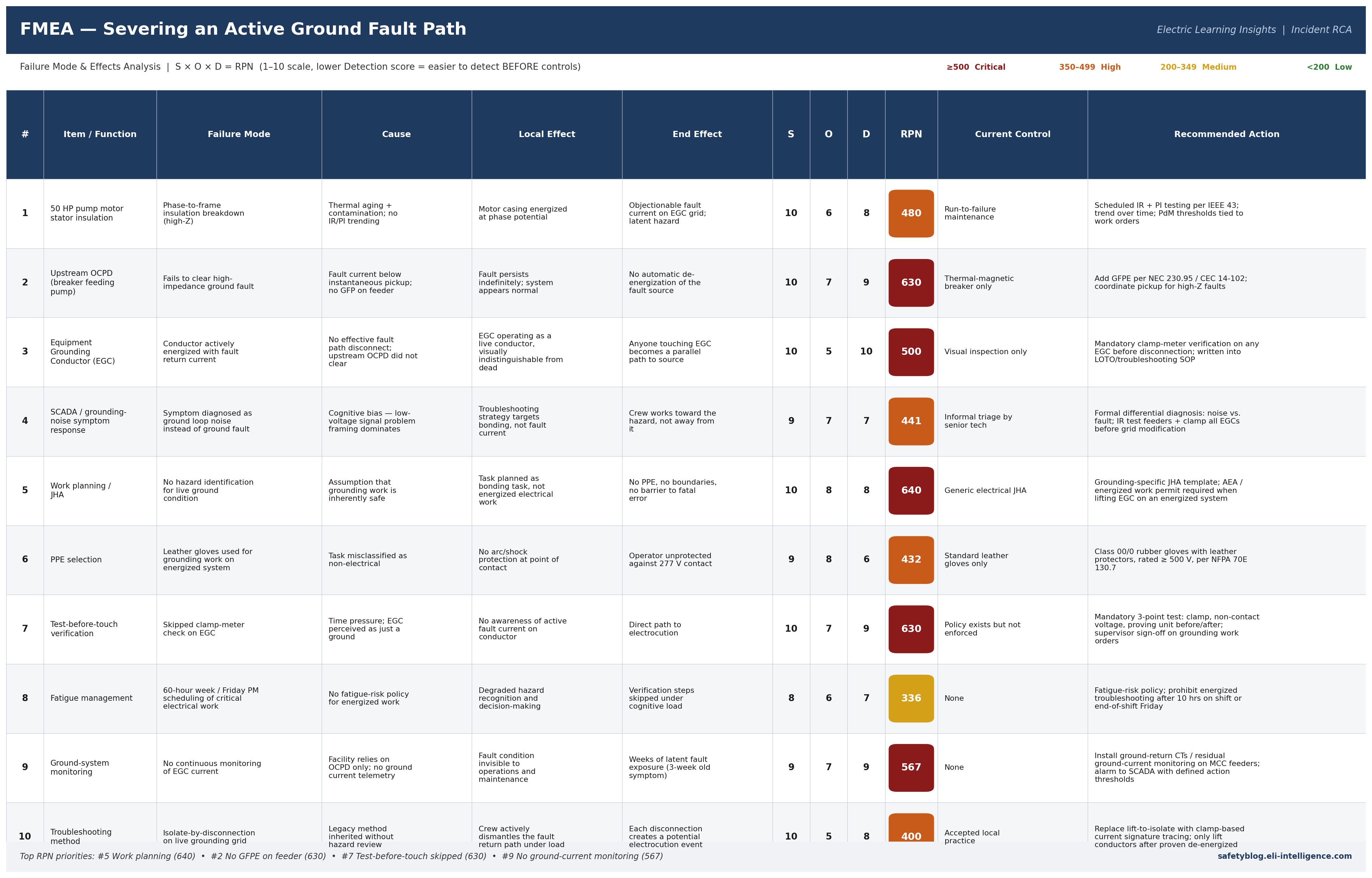 Click to enlarge — 10 failure modes scored on S × O × D = RPN
Top RPN priorities (where the risk actually lives):
- Work planning / JHA (RPN 640) — The chain starts here. Grounding-system work on an energized distribution system must be classified as energized electrical work, full stop.
- No GFPE on the feeder (RPN 630) — The hard engineering fix. If the breaker had cleared the high-impedance fault, nothing downstream in this table matters.
- Test-before-touch skipped (RPN 630) — The last-line administrative control that would have saved him independent of everything upstream. A five-second clamp-meter check.
- No continuous ground-current monitoring (RPN 567) — Would have turned a three-week latent fault into a maintenance ticket instead of a fatality.
The pattern is structural: two engineering gaps (GFPE, ground-current monitoring) plus three procedural gaps (JHA scope, test-before-touch, isolation method) combined to enable this fatality. No single person failed — the system was designed in a way that made this outcome available.
7. Actionable Conclusion
- Always Clamp Grounds Before Lifting: Never disconnect an equipment grounding conductor, system bonding jumper, or neutral wire without first checking it with a clamp meter. If it is carrying current, do not touch it. Treat any non-zero reading as a live conductor until the source fault is identified and cleared.
- Treat Grounds as Live Potential: Assume every conductor is energized until you prove otherwise. A ground wire carrying fault current operates at line voltage the instant you break its connection. The green jacket does not make it safe.
- Trace the Fault First — Do Not Dismantle: Never attempt to “troubleshoot” objectionable current by blindly unbolting ground paths. You are dismantling the facility’s life safety net while the system is powered. Use clamp-based current signature tracing on the energized grid to locate the source, then de-energize before any disconnection.
- Install the Engineering Backstop: If your 480Y/277V service falls under NEC 230.95 / CEC 14-102, verify GFPE is installed, calibrated, and coordinated to clear high-impedance faults that fall below instantaneous breaker pickup. This is the layer that catches what insulation testing misses.
Free resource: Objectionable Current Investigation Checklist
Want to prevent this scenario on your site? Download the field-ready Grounding-System Objectionable Current Investigation Checklist. Built around IEEE 142, NEC 250 / CEC Section 10, and NFPA 70E / CSA Z462 test-before-touch principles, it walks you through diagnosing ground-system symptoms without dismantling the fault return path under load.
Community Discussion
Join the conversation. What are your thoughts on this incident or safety topic?
Comments will appear here once the Giscus GitHub repository is linked.