
The Silent Shock: Why a 'Tingling' Drill Rig is a Deadly Warning
A minor tingle on a mining drill rig isn't static electricity — it's an active equipment bonding failure. Learn how a fractured trailing cable and a failed ground-check monitor combined to defeat every layer of protection underground.
The Silent Shock: Why a “Tingling” Drill Rig is a Deadly Warning
1. The Flashpoint
At 2:00 AM on a graveyard shift, an experienced underground drill operator reached out to steady himself against the chassis of his 1000-volt drill rig and was met with a sharp, pulsating light shock. He shook it off — static, he figured — and kept working. He was standing inches away from a catastrophic double-failure: a fractured grounding conductor inside the trailing cable and a ground-check monitor with welded-shut contacts. Two independent safety systems had failed silently. The rig’s chassis was energized, and every protection layer between the operator and a potentially fatal shock was already gone.
2. The Environment That Enables Failure
Deep underground, every condition works against electrical integrity. The drift was damp, humid, and lined with welded wire mesh ground support — all of it conductive. The mobile drill rig had been running continuously through the shift, subjected to severe vibration, heat cycling, and mechanical stress that no surface installation would tolerate.
The drill rig was fed via a type SHD-GC trailing cable — the industry standard for mobile mining equipment. SHD-GC cable carries three critical functions in one jacket: the three phase power conductors, equipment grounding conductors (EGC’s) for fault return, and a central pilot wire monitored by a ground-fault ground-check (GFGC) relay. If required, the GFGC system can supervise and monitor two things simultaneously: ground-fault current magnitude and the integrity of the ground-check loop — the complete circuit formed by the pilot conductor, coupler connections, termination device, grounding conductor, and return path. The ground check circuit is a mandated minimum by the CSA M421 standard.
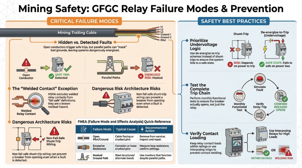
If that loop breaks — a severed pilot wire, a failed coupler pin, a fractured EGC — the GFGC relay is supposed to declare the loop invalid and trip the supply breaker instantly. That is the system’s final line of defense. MSHA’s fail-safe concept is built around exactly this: the breaker opens when the ground or pilot conductor is broken.
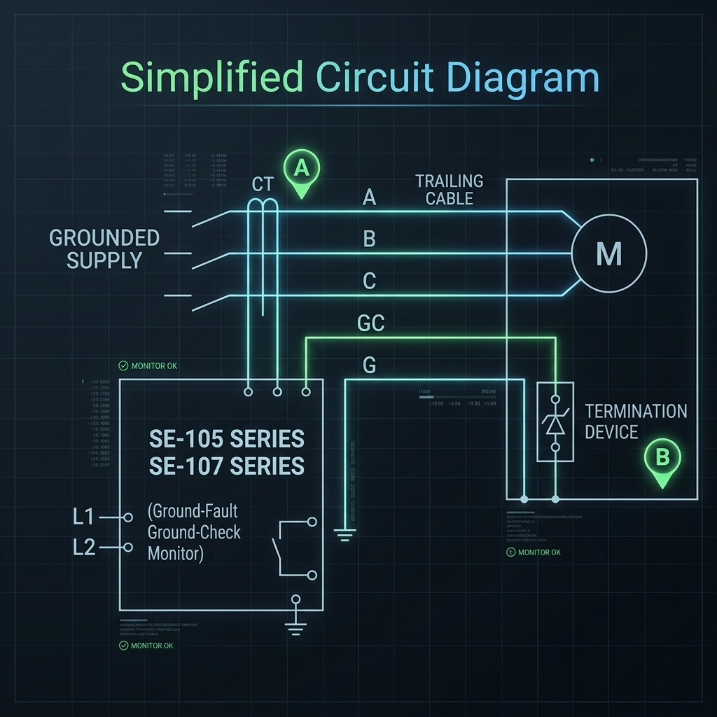
Legend: A - Ground Fault CT | B - Ground Check Termination Device Zener Diode
(Image Credit: Littelfuse Startco SE-105/107 Manual)
The crew — fatigued, focused on production, and accustomed to the minor electrical oddities common underground — had no reason to suspect that both the grounding path and the monitor designed to detect its failure had already been compromised.
3. How Two Independent Failures Combined
-
The creeping wear. Weeks of dragging the trailing cable across fractured rock had caused progressive micro-abrasions to the outer jacket and insulation. Each shift added cumulative mechanical damage invisible from the outside.
-
The fractured ground path. Inside the cable, the equipment grounding conductor and the central pilot wire suffered degradation and eventual fracture from continuous tensile stress during cable reeling and dragging. The designated low-impedance fault return path to the substation was compromised and functioning intermittently. The ground-check loop — the circuit the GFGC relay depends on to verify protection integrity — was broken. Under normal operation, this single failure should have been detected and safely-tripped the drill power supply immediately.
-
The blind monitor. The minimal ground check (GC) monitoring function — specifically mandated by CSA M421 and MSHA to detect exactly this failure — had itself failed catastrophically. Its failsafe de-energized normally open output contacts had welded shut under repeated intermittent trips, resets, and load cycling. With the contacts welded closed, the relay could no longer open the contacts to the main breaker supply. It was electrically blind and malfunctioning. The pilot wire was broken, and the monitor that existed to catch that break could not respond as designed. This is one of the most dangerous hidden failure modes in trailing cable protection — and MSHA’s own acceptance criteria explicitly acknowledge it by excluding welded relay contacts from the general fail-safe definition.
-
The insulation breakdown. A high-impedance phase-to-ground fault developed in the rig’s 1,000V main drive motor. Vibration and thermal cycling had degraded the stator winding insulation over time, creating an extremely small current leakage path from the energized winding to the motor frame and from there to the entire rig chassis.
-
The energized chassis. Even though the circuitry of the GFGC was functionally tripped the welded closed relay output contacts not trip the breaker by opening its contacts. The rig’s metallic chassis sat at a dangerous touch potential relative to the mine ground surface. The damp earth and welded wire mesh provided a slight parallel return path — enough to sustain a small current and voltage. When the operator touched the chassis, his body completed a more conductive path through the damp ground. The “tingle” he felt was a potentially lethal fault current flowing through him. Note that it only takes as little as 50ma of current to be potentially fatal.
Guess the Root Cause
When an operator reports a 'tingle' when touching grounded industrial machinery, what should be the immediate first step for the electrical team?
4. Direct, Systemic, and Organizational Causes
Direct cause: A high-impedance phase-to-ground fault in the rig’s drive motor energized the chassis at dangerous touch potential. This fault persisted because of a concurrent double-failure: the EGC and pilot wire inside the SHD-GC trailing cable had fractured from mechanical stress, and the GFGC relay’s output contacts had welded shut. Neither the ground-fault protection nor the ground-check monitor could operate. Every layer of automatic protection was defeated.
Systemic cause — inspection, maintenance, and design gaps:
No condition-based cable inspection protocol. The trailing cable inspection program was calendar-based (quarterly). There was no protocol tying inspection frequency to drag distance, operating hours, or environmental severity — all of which were extreme in this application. A regime aligned to actual cable stress would have detected the EGC degradation before fracture. End-to-end loop resistance measurement — not just continuity — is critical, because excessive resistance from broken strands, corroded pins, or degraded splices can allow unsafe frame voltages even before a full conductor break.
No functional testing of the complete GFGC trip chain. The relay’s welded contacts went undetected because the relay was never subjected to end-to-end functional testing. MSHA regulations explicitly require monthly testing and examination of circuit breakers and auxiliary devices — including physically breaking ground-check continuity and verifying that the relay detects the break, the auxiliary contacts respond, and the breaker opens. A relay indicator light showing “healthy” does not prove the trip chain functions. The indicator confirms the relay’s internal logic detected the condition. It does not confirm the output contacts can move, the trip coil will energize, or the breaker mechanism will operate. Only an end-to-end test proves the system works.
There is a critical additional layer beyond the GFGC relay: the breaker’s own undervoltage release (UVR) mechanism. MSHA warns that ground-fault, ground-wire monitor, and undervoltage protection circuits all rely on the UVR relay — and if that relay is damaged or improperly adjusted, the safety circuits cannot operate the breaker regardless of whether the GFGC relay functions correctly. Testing the relay alone is insufficient. The complete trip chain from sensor to breaker must be verified.
Fail-safe design requires undervoltage release (UVR) — also called de-energize-to-trip — where the breaker is held closed by a continuously energized coil. Any interruption (welded contacts, broken wiring, loss of control power, relay failure) causes the coil to drop out and the breaker to open automatically. MSHA also recognizes ground-check relays as acceptable for undervoltage protection when they trip at 40–60% of nominal line voltage.
Organizational cause — no stop-work mechanism: The site had no mandatory stop-work protocol triggered by electrical anomaly reports. When the operator and crew members felt tingling on the rig, no procedure existed requiring them to isolate the equipment and initiate an electrical investigation. The warning was treated as a crew judgment call rather than an automatic trigger. The workers detected the hazard. The management system failed to provide a mechanism to act on it.
Recurring patterns in industry: This combination of failure modes is well-documented: Parallel ground paths masking degraded cable grounds. MSHA identifies this as one of the most subtle and dangerous failure modes. Some monitor types — particularly impedance and resistance monitors — can be satisfied by unintended parallel return paths through steel structures, secondary bonds, or alternate ground connections. The relay appears healthy. The intended cable ground path is compromised. Components installed between the power center and the machine can defeat the purpose of the monitor if not treated correctly. This means the relay can be fooled into seeing an acceptable loop even though the cable ground path is degraded to the point of being dangerous.
5. Actionable Protocols for Your Site
Mandatory stop-work on any shock report. Any worker who feels a tingle, shock, or abnormal sensation when touching equipment initiates a stop-work. The equipment is isolated and locked out immediately — before any investigation. A tingle is an active ground fault. The absence of a relay trip is itself the danger signal.
Condition-based trailing cable inspections. Move beyond calendar-based schedules. Tie EGC and pilot wire testing to drag distance, operating hours, and environmental severity. Measure end-to-end loop resistance, not just continuity — excessive resistance from broken strands, corroded pins, or degraded splices can create unsafe frame voltages before a full conductor break. Document every test with date, measured values, and pass/fail against baseline.
Monthly functional testing of the complete GFGC trip chain. Do not rely on relay indicator lights. Comply with MSHA requirements: physically break the pilot circuit at the equipment end and verify that the GFGC relay detects the loss of continuity, the auxiliary contacts respond, and the supply breaker opens. Then go further — verify the breaker’s UVR mechanism operates correctly, because a healthy relay cannot trip a damaged breaker. Test the entire chain from sensor to breaker. Log every test.
Torque-verified bonding inspections. For all mobile and stationary equipment subject to vibration, verify ground lugs and bonding jumpers at every scheduled maintenance interval with a calibrated torque wrench — not just a visual check. Inspect coupler pins for wear and verify pilot-first / ground-last sequencing where required. A connection tight at installation vibrates loose in service.
Verify termination devices and coupler integrity. GFGC systems depend on a recognized termination assembly at the load end. Confirm the correct approved device is installed, undamaged, and properly connected. Replace worn or damaged couplers and verify pilot-first / ground-last behavior during uncoupling.
6. Advanced Architectures: Could SIL and 2oo3 Logic Work Here?
For highly critical trailing cable applications like massive production drills or continuous miners, relying on a single GFGC relay introduces a single point of failure (like the welded contact in this incident). An increasingly discussed approach is applying functional safety methodologies—specifically Safety Integrity Level (SIL) ratings and Two-out-of-Three (2oo3) voting logic.
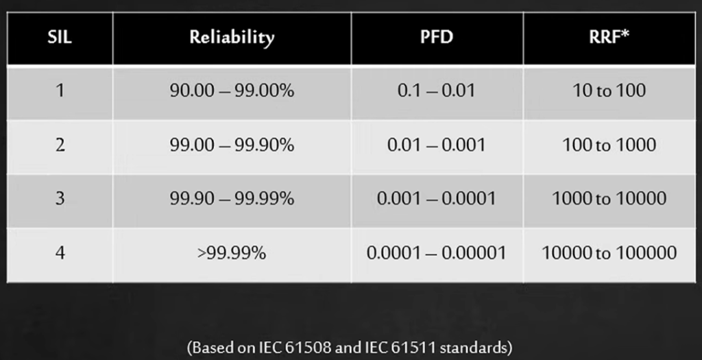
Typical SIL, Reliability, PFD, and Risk Reduction Factor (RRF) values based on IEC 61508 / 61511 standards.
Because of how the underlying circuit monitoring works, you cannot simply wire three separate GFGC relays to the same pilot loop—they would interfere with each other. However, alternative methods are possible without astronomical expense.
The question for site electrical/controls professionals: Can we engineer cost-effective SIL architectures for trailing cable monitoring to eliminate these single points of failure, or is a rigorous monthly functional test of a standard relay sufficient? Let us know your thoughts in the comments or on LinkedIn.
7. Failure Modes and Effects Analysis (FMEA)
Every significant failure mode in a mining trailing-cable GFGC scheme — from detected safe-trip faults to dangerous hidden failures — mapped to root cause, consequence, detection method, and recommended control. Click to open the full analysis.
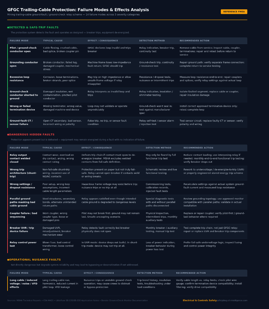 Click to enlarge — GFGC relay FMEA covering 14 failure modes across three severity categories
📥 Click here to download the High-Resolution FMEA Table for printing
Free resource: Trailing-cable GFGC inspection and test checklist
Want to prevent these hidden failures on your site? Download our field-ready Trailing-Cable GFGC / Ground-Check Inspection and Test Checklist (PDF). Built around CSA M421 and MSHA requirements, it covers the complete trip chain — from pilot wire continuity through relay function to breaker UVR operation — with pass/fail fields and step-by-step test procedures.
🎁 BONUS: Subscribe to our ELI Safety Alerts below, and we’ll instantly email you the free GFGC Checklist PDF along with our daily safety topics and RCAs!
Community Discussion
Join the conversation. What are your thoughts on this incident or safety topic?
Comments will appear here once the Giscus GitHub repository is linked.