
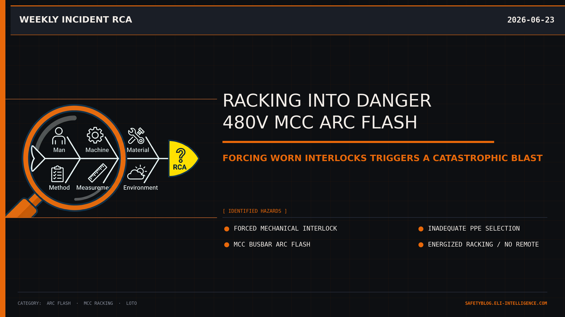
Racking Into Danger: The 480V MCC Arc Flash
A routine breaker racking operation turned into a catastrophic arc flash when a misaligned cell interlock was forced on a live motor control center.
1. The Hook (Flashpoint)
At 2:14 PM, a loud, thunderous boom echoed through the electrical substation of an oil refinery as a massive 480V arc flash erupted from a Motor Control Center (MCC) column. The blast blew the steel door off the compartment, engulfing a senior maintenance technician in a fireball and leaving him with severe second- and third-degree burns across his upper body.
2. The Setup
The day shift had been running smoothly, but fatigue was setting in as the crew entered their ninth hour on site. The weather outside was a humid 88°F, and inside the substation, the air conditioning was struggling to keep the ambient temperature below 75°F.
The task at hand was routine: rack in a refurbished 100A feeder circuit breaker bucket back into a live 480-volt, 3-phase MCC stack to restore power to a cooling water pump. The maintenance team consisted of the senior technician and an apprentice. Both were wearing standard 8-cal/cm² Category 2 daily arc flash PPE, safety glasses, and leather work gloves. However, they had not donned the heavy-duty 40-cal arc flash suits or voltage-rated rubber gloves, as they believed the mechanical interlocks of the breaker bucket would prevent any hazardous contact during the racking process.
3. The Breakdown
- The Racking Setup: The technician opened the compartment door and positioned the refurbished breaker bucket inside the MCC guide rails, preparing to wind the racking screw to connect the bucket’s rear “stabs” to the live vertical copper busbars.
- The Interference: As he began to turn the racking handle, the mechanism bound up. The breaker’s internal mechanical interlock—designed to prevent racking while the breaker contacts are closed—was misaligned due to wear on the plunger rod.
- The Forced Entry: Believing the binding was just typical dirt in the guide tracks, the technician applied significant torque to the racking handle, forcing the racking screw past the mechanical resistance.
- The Fault Injection: Unknown to the technician, forcing the handle defeated the safety interlock and pushed the breaker stabs into the vertical busbars while the breaker’s internal contacts were closed under a heavy downstream load.
- The Blast: The sudden connection under load drew a severe electrical arc between the breaker stabs and the live busbars. Superheated copper vaporized instantly, expanding 67,000 times in volume and generating an arc flash that reached temperatures of 35,000°F, blowing the bucket out of the cell and severely injuring the technician.
4. Interactive Quiz
Guess the Root Cause
What was the primary technical failure that allowed the arc flash to occur during racking?
5. The RCA
Direct Cause: The direct cause was a phase-to-phase and phase-to-ground short circuit created when the breaker stabs engaged the live vertical busbars while the breaker contacts were closed.
Systemic/Human Cause: The root cause was a failure in the facility’s maintenance procedures and safety culture. The refurbished breaker bucket had not undergone pre-installation quality control or mechanical alignment testing. Furthermore, a culture of normalizing deviations led the technician to force a binding racking mechanism rather than stopping to investigate the resistance. Finally, the facility lacked a mandate for “closed-door racking” or remote racking systems, which would have physically isolated the worker from the blast zone.
6. Failure Modes and Effects Analysis (FMEA)
(Note: FMEA rendering to be completed by Claude editorial agent prior to publication).

7. Applicable Codes & Standards
- NFPA 70E Article 130.2 — Establishing an Electrically Safe Work Condition: Racking a breaker in or out of a live bus is considered energized electrical work.
- NFPA 70E 130.5 — Arc Flash Risk Assessment: Requires determining the arc flash boundary and the required PPE rating before performing racking operations.
- OSHA 29 CFR 1910.303(b)(2) — Suitability of Equipment: Requires that electrical equipment be installed and maintained in accordance with manufacturer instructions.
- CSA Z462 Clause 4.3 — Work involving electrical hazards: Establishes the hierarchy of risk control, emphasizing substitution (such as remote racking) and engineering controls (like closed-door racking mechanisms) over relying solely on PPE.
- IEEE 1584 — Guide for Performing Arc-Flash Hazard Calculations: Standard used to calculate the incident energy levels at the working distance.
8. Free Resource
[Lead magnet CTA — Claude]
Download the MCC Racking & Isolation Safety Checklist
9. Actionable Takeaways
- Stop on Resistance: Never apply force or use cheater bars on racking handles. If a racking mechanism binds, stop immediately, rack the bucket back out, and inspect the alignment of the mechanical interlocks and guide rails.
- Implement Remote Racking: Transition to remote racking systems that allow technicians to wind breakers in or out from outside the substation room or beyond the arc flash boundary.
- Verify Mechanical Tolerances: Ensure all new or refurbished breaker buckets undergo documented mechanical inspection and interlock verification before being placed into service on live buses.
10. Conclusion
A mechanical safety interlock is a critical barrier, but it is not indestructible; if you force it to yield, the electrical system will respond with catastrophic force.
Community Discussion
Join the conversation. What are your thoughts on this incident or safety topic?
Comments will appear here once the Giscus GitHub repository is linked.